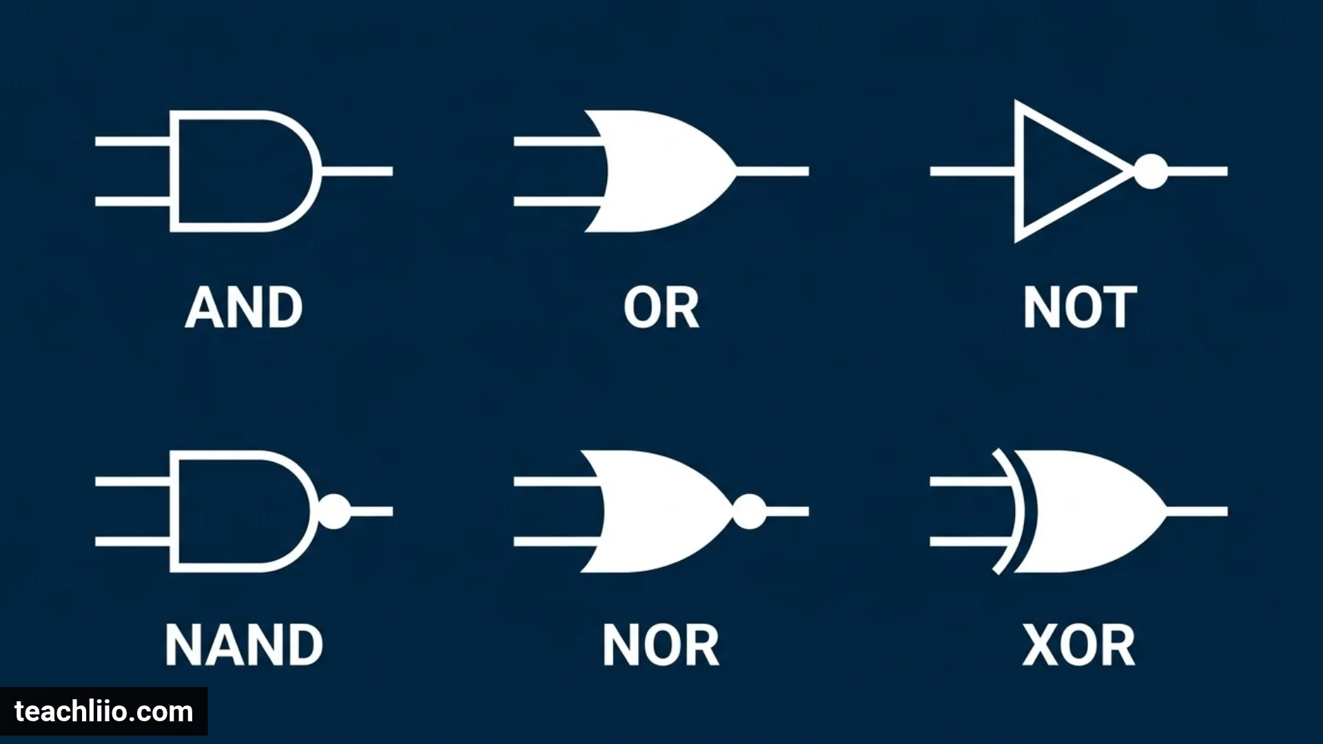
Logic gates symbols are graphical representations of the basic operations used in digital electronic circuits. They show how electronic systems process binary information and produce outputs based on different input conditions. The seven commonly used logic gates are AND, OR, NOT, NAND, NOR, XOR, and XNOR. Each gate has a unique symbol, Boolean expression, and truth table that explains its operation.
Understanding logic gate symbols is important for students, electronics beginners, computer engineering learners, and anyone studying digital circuit design. These symbols make it easier to read circuit diagrams, understand Boolean algebra, identify electronic components, and learn how computers process information.
For example, an AND gate produces an output of 1 only when all its inputs are 1, while an OR gate produces 1 when at least one input is 1. A NOT gate reverses its input, and NAND and NOR gates perform inverted logical operations.
In this complete guide, you will learn the names and functions of logic gates, recognize their symbols, understand their truth tables, compare ANSI and IEC symbol standards, and explore practical circuit examples. We will also cover buffer gates, tri-state symbols, Boolean expressions, universal gates, and commonly used logic gate ICs.
What Are Logic Gates Symbols?
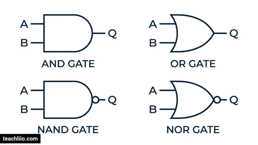
Logic gate symbols are standardized graphical shapes used to represent logical operations in digital electronic circuits. Each symbol shows how one or more binary inputs are processed to produce a single output.
Digital electronics uses two basic logic states:
- 0 (LOW): Represents a false or low logic state.
- 1 (HIGH): Represents a true or high logic state.
A logic gate receives these binary signals and follows a specific logical rule to determine its output. Engineers use gate symbols to represent these operations in circuit diagrams without drawing the internal transistor arrangements.
For example, an AND gate has two or more inputs and produces an output of 1 only when every input is 1. A NOT gate has one input and produces the opposite value.
Logic gates are commonly constructed using transistors and are used in computers, calculators, smartphones, memory systems, industrial controllers, and other digital devices.
Complete Logic Gates Symbols Chart
There are seven basic logic gates that every digital electronics student should recognize. The following chart provides their names, traditional symbol descriptions, and Boolean expressions.
| Logic gate | Traditional symbol appearance | Boolean expression |
| AND | D-shaped body | Y = A · B |
| OR | Curved input, pointed output | Y = A + B |
| NOT | Triangle with output bubble | Y = Ā |
| NAND | AND shape with output bubble | Y = (A · B)̅ |
| NOR | OR shape with output bubble | Y = (A + B)̅ |
| XOR | OR shape with extra curved line | Y = A ⊕ B |
| XNOR | XOR shape with output bubble | Y = (A ⊕ B)̅ |
The small circle on a symbol is called an inversion bubble. It indicates that the signal is logically inverted at that point.
How to Recognize Logic Gate Symbols
You can identify most traditional logic gate symbols by looking at their shapes.
- AND: A flat input side and a rounded output side.
- OR: A curved input side and a pointed output side.
- NOT: A triangle with a small circle at its output.
- NAND: An AND symbol with a small output circle.
- NOR: An OR symbol with a small output circle.
- XOR: An OR symbol with an additional curved line.
- XNOR: An XOR symbol with a small output circle.
These are the distinctive-shape symbols commonly found in electronics textbooks and circuit diagrams.
7 Basic Logic Gates Symbols and Their Functions
Each basic logic gate performs a different operation. Understanding its symbol, Boolean expression, and truth table will help you recognize gates in digital circuit diagrams.
1. AND Gate Symbol
The AND gate is one of the most important logic gates in digital electronics. Its traditional symbol has a flat left side and a rounded right side, creating a D-shaped appearance.
An AND gate produces an output of 1 only when all its inputs are 1. If one or more inputs are 0, the output is 0.
Boolean expression:
Y = A · B
Truth table:
| Input A | Input B | Output Y |
| 0 | 0 | 0 |
| 0 | 1 | 0 |
| 1 | 0 | 0 |
| 1 | 1 | 1 |
Example: Imagine an electronic security system that requires two switches to be activated before a door opens. Both switches must be ON for the output to become 1.
Applications: Digital control systems, safety circuits, condition-checking systems, and electronic switching.
2. OR Gate Symbol
The OR gate has a curved input side and a pointed output side. It is easy to distinguish from the AND gate because of its curved shape.
An OR gate produces an output of 1 when at least one input is 1. Its output is 0 only when all inputs are 0.
Boolean expression:
Y = A + B
Truth table:
| Input A | Input B | Output Y |
| 0 | 0 | 0 |
| 0 | 1 | 1 |
| 1 | 0 | 1 |
| 1 | 1 | 1 |
Example: Consider an alarm system connected to two sensors. If either sensor detects a problem, the alarm receives an active signal.
Applications: Alarm systems, digital decision circuits, and sensor control systems.
3. NOT Gate Symbol
The NOT gate is also known as an inverter because it reverses the input signal. Its traditional symbol consists of a triangle with a small circle at the output.
Unlike most other basic logic gates, a NOT gate has only one input.
Boolean expression:
Y = Ā
Truth table:
| Input A | Output Y |
| 0 | 1 |
| 1 | 0 |
Example: When the input is 1, the output becomes 0. When the input is 0, the output becomes 1.
Applications: Signal inversion, digital switching, and control circuits.
4. NAND Gate Symbol
NAND stands for NOT AND. Its traditional symbol looks like an AND gate with a small circle at the output.
It first performs the AND operation and then reverses the result. Therefore, its output is 0 only when all inputs are 1.
Boolean expression:
Y = (A · B)̅
Truth table:
| Input A | Input B | Output Y |
| 0 | 0 | 1 |
| 0 | 1 | 1 |
| 1 | 0 | 1 |
| 1 | 1 | 0 |
Example: A NAND gate produces an output of 0 when both input conditions are active. For all other combinations, its output is 1.
Applications: Memory circuits, digital processors, switching systems, and integrated circuits.
5. NOR Gate Symbol
NOR stands for NOT OR. Its symbol resembles an OR gate but includes a small circle at the output.
A NOR gate performs the OR operation and then inverts the result. It produces an output of 1 only when all inputs are 0.
Boolean expression:
Y = (A + B)̅
Truth table:
| Input A | Input B | Output Y |
| 0 | 0 | 1 |
| 0 | 1 | 0 |
| 1 | 0 | 0 |
| 1 | 1 | 0 |
Example: A NOR-based control circuit can produce an active output when neither of its two input signals is active.
Applications: Digital control systems, memory circuits, and electronic switching.
6. XOR Gate Symbol
XOR stands for Exclusive OR. Its traditional symbol looks like an OR gate with an additional curved line on the input side.
For two inputs, an XOR gate produces an output of 1 when the inputs are different. When both inputs are equal, the output is 0.
Boolean expression:
Y = A ⊕ B
Truth table:
| Input A | Input B | Output Y |
| 0 | 0 | 0 |
| 0 | 1 | 1 |
| 1 | 0 | 1 |
| 1 | 1 | 0 |
Example: A digital system can use XOR logic to identify whether two binary signals have different values.
Applications: Half adders, parity generators, binary arithmetic, and error detection.
7. XNOR Gate Symbol
XNOR stands for Exclusive NOR. Its symbol resembles an XOR gate but has a small inversion bubble at the output.
An XNOR gate produces an output of 1 when its two inputs are equal. If the inputs are different, the output becomes 0.
Boolean expression:
Y = (A ⊕ B)̅
Truth table:
| Input A | Input B | Output Y |
| 0 | 0 | 1 |
| 0 | 1 | 0 |
| 1 | 0 | 0 |
| 1 | 1 | 1 |
Example: An XNOR gate can help a digital circuit check whether two binary values match.
Applications: Equality comparators, digital comparison systems, and error-checking circuits.
Other Important Digital Logic Symbols
Besides the seven basic gates, digital circuit diagrams include other logic elements that perform specialized functions. These symbols are useful when studying practical electronics and more advanced digital systems.
Buffer Gate Symbol
A buffer is represented by a triangle without an inversion bubble at the output. Unlike a NOT gate, it does not reverse the input signal.
Boolean expression:
Y = A
| Input A | Output Y |
| 0 | 0 |
| 1 | 1 |
Buffers are used for signal isolation, signal distribution, and driving loads that require more current than a preceding circuit can provide.
Tri-State Buffer Symbol
A tri-state buffer is a special digital circuit that can produce three possible output conditions:
- 0 (LOW)
- 1 (HIGH)
- Z (High impedance)
The third state, called high impedance, allows the output to behave as if it is electrically disconnected from a shared signal line.
A tri-state buffer generally has a data input, an enable input, and an output. Its symbol is similar to a buffer triangle but includes an enable connection.
The enable input may be active-high or active-low, depending on the device.
Applications: Shared data buses, computer memory interfaces, and digital communication systems.
Tri-State Inverter Symbol
A tri-state inverter combines signal inversion with an enable function. When enabled, it produces the opposite of the input. When disabled, it places the output in the high-impedance state.
This is useful in digital systems where multiple devices share a communication line.
Schmitt Trigger Symbol
A Schmitt trigger is a logic input circuit with hysteresis. It uses different switching thresholds for rising and falling input signals.
Its symbol is commonly based on an inverter or buffer shape with an additional hysteresis indication.
Why is it useful?
- Reduces the effect of noisy input signals.
- Helps clean up slowly changing signals.
- Improves switching reliability.
- Converts imperfect input waveforms into cleaner digital signals.
Schmitt triggers are often used in switch debouncing, signal conditioning, and digital input circuits.
Three-Input and Multi-Input Logic Gates
Logic gates can have more than two inputs. Their symbols keep the same basic shape, but additional input connections are added.
For example:
- Three-input AND: Y = A · B · C
- Three-input OR: Y = A + B + C
- Three-input NAND: Y = (A · B · C)̅
- Three-input NOR: Y = (A + B + C)̅
The same principle applies to gates with four or more inputs.
Logic Gates Truth Tables
A truth table shows every possible combination of binary inputs and the corresponding output of a logic gate.
Truth tables are important because they allow students and engineers to understand, verify, and compare logical operations.
Complete Two-Input Logic Gates Truth Table
The following table compares all seven basic logic gates using two inputs.
| A | B | AND | OR | NAND | NOR | XOR | XNOR |
| 0 | 0 | 0 | 0 | 1 | 1 | 0 | 1 |
| 0 | 1 | 0 | 1 | 1 | 0 | 1 | 0 |
| 1 | 0 | 0 | 1 | 1 | 0 | 1 | 0 |
| 1 | 1 | 1 | 1 | 0 | 0 | 0 | 1 |
The NOT gate is represented separately because it has only one input.
| A | NOT |
| 0 | 1 |
| 1 | 0 |
Three-Input AND Gate Truth Table
A three-input gate has eight possible input combinations because each input can be either 0 or 1.
| A | B | C | Output Y |
| 0 | 0 | 0 | 0 |
| 0 | 0 | 1 | 0 |
| 0 | 1 | 0 | 0 |
| 0 | 1 | 1 | 0 |
| 1 | 0 | 0 | 0 |
| 1 | 0 | 1 | 0 |
| 1 | 1 | 0 | 0 |
| 1 | 1 | 1 | 1 |
Only the final combination produces an output of 1 because all three inputs must be active.
How to Calculate Truth Table Rows
You can calculate the number of possible input combinations using this formula:
Number of combinations = 2ⁿ
Here, n represents the number of inputs.
| Number of inputs | Possible combinations |
| 1 | 2 |
| 2 | 4 |
| 3 | 8 |
| 4 | 16 |
| 5 | 32 |
| 6 | 64 |
This formula works for any circuit with n independent binary inputs.
ANSI/IEEE vs IEC Logic Gate Symbols
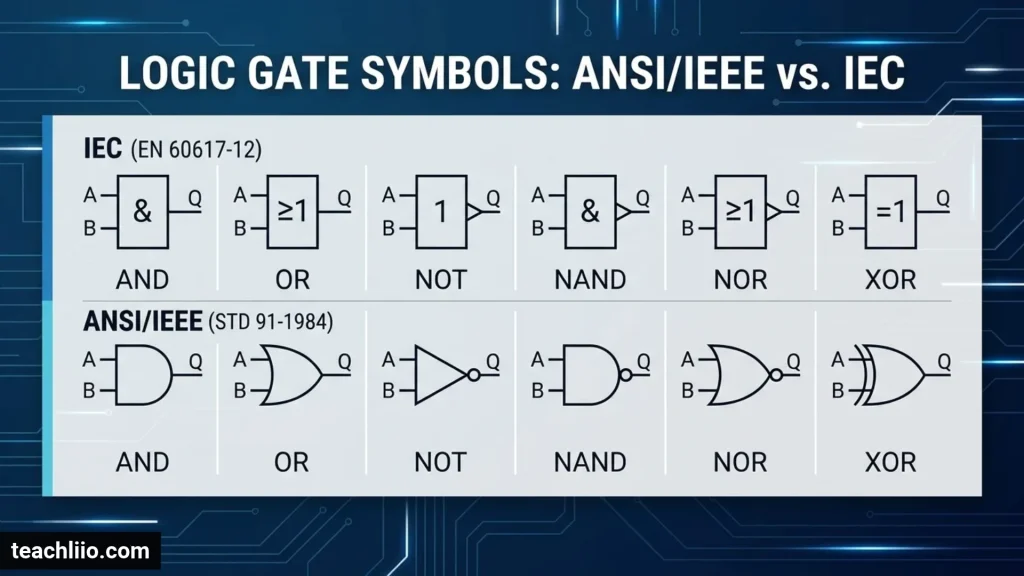
Logic gates can be represented using different graphical standards. Two common approaches are distinctive-shape notation and rectangular function notation.
Although their symbols look different, they represent the same logical operations.
ANSI/IEEE Distinctive-Shape Symbols
Traditional distinctive-shape notation is widely used in American electronics textbooks and circuit diagrams.
Its symbols are identified by their shapes:
- AND uses a D-shaped body.
- OR uses a curved, pointed body.
- NOT uses a triangle with an inversion bubble.
- NAND uses an AND symbol with an output bubble.
- NOR uses an OR symbol with an output bubble.
- XOR uses an OR symbol with an additional curved line.
- XNOR uses an XOR symbol with an output bubble.
IEC Rectangular Symbols
IEC notation generally uses rectangular gate bodies containing function labels.
Common labels include:
| Gate | Common IEC function label |
| AND | & |
| OR | ≥1 |
| XOR | =1 |
| NOT | Inversion indication |
| NAND | & with output inversion |
| NOR | ≥1 with output inversion |
| XNOR | =1 with output inversion |
The symbol =1 is commonly used for the two-input exclusive-OR function. When dealing with more inputs, always check the exact function definition instead of assuming every XOR convention means exactly one input is high.
Which Symbol Standard Should You Learn?
Both notations are important.
Students should learn the distinctive shapes because they are common in introductory electronics education. They should also understand rectangular IEC notation because it appears in technical drawings and engineering documentation.
The most important skill is recognizing the logical function regardless of the drawing style.
Boolean Algebra Symbols Used in Logic Gates
Boolean algebra is the mathematical system used to describe logical operations in digital electronics. It uses binary variables and special operators to express how logic gates work.
The most common Boolean symbols include:
| Symbol | Operation | Meaning |
| · | AND | Both conditions must be true |
| + | OR | At least one condition must be true |
| Bar above a variable | NOT | Reverses the value |
| ⊕ | XOR | Inputs differ for two-input operation |
| = | Equality | Shows equivalent expressions |
| ( ) | Grouping | Controls the order of operations |
For example:
AND operation: Y = A · B
OR operation: Y = A + B
NOT operation: Y = Ā
NAND operation: Y = (A · B)̅
NOR operation: Y = (A + B)̅
XOR operation: Y = A ⊕ B
Understanding these operators makes it easier to convert Boolean expressions into circuit diagrams and vice versa.
What Does the Inversion Bubble Mean in a Logic Gate Symbol?
A small circle on a logic gate symbol is called an inversion bubble. It indicates that the signal is logically inverted at that point.
For example, an AND gate with an output bubble becomes a NAND gate. An OR gate with an output bubble becomes a NOR gate.
The position of the bubble is important.
Output Inversion
When the bubble appears at the output, the gate’s result is reversed.
Examples:
- AND becomes NAND.
- OR becomes NOR.
- XOR becomes XNOR.
Input Inversion
When the bubble appears at an input, that particular input is inverted before the gate performs its operation.
For example, a two-input AND gate with an inverted A input produces:
Y = Ā · B
Active-High and Active-Low Signals
An active-high signal is considered active when its value is 1.
An active-low signal is considered active when its value is 0.
Active-low signals are commonly shown using an inversion bubble or a bar over the signal name. They are used in reset, enable, control, and communication circuits.
Recognizing these symbols helps prevent mistakes when reading complex electronic diagrams.
Difference Between Similar Logic Gates
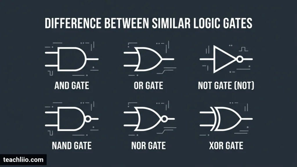
Some logic gates have similar symbols and operations, which can make them confusing for beginners.
The following comparison highlights their main differences.
| Gate comparison | Main difference |
| AND vs OR | AND requires all inputs to be 1; OR requires at least one |
| AND vs NAND | NAND reverses the AND output |
| OR vs NOR | NOR reverses the OR output |
| XOR vs OR | XOR produces 1 only when two inputs differ |
| XOR vs XNOR | XNOR produces the opposite output of XOR |
| NOT vs Buffer | NOT reverses the input; Buffer preserves it |
| NAND vs NOR | NAND is inverted AND; NOR is inverted OR |
A simple way to remember these differences is to study the truth tables together rather than memorizing the symbols separately.
Why Are NAND and NOR Called Universal Logic Gates?
NAND and NOR are known as universal logic gates because either type can be used alone to construct all the basic Boolean operations.
This property makes them important in digital electronics and integrated circuit design.
Building Other Gates Using NAND
You can create other logical operations using only NAND gates.
NOT using NAND:
Connect both inputs to the same signal.
Y = (A · A)̅ = Ā
AND using NAND:
First use a NAND gate, then invert its output using another NAND gate.
Y = ((A · B)̅)̅ = A · B
OR using NAND:
Using De Morgan’s law:
Y = (Ā · B̅)̅ = A + B
Building Other Gates Using NOR
NOR gates can also construct the basic operations.
NOT using NOR:
Y = (A + A)̅ = Ā
OR using NOR:
Invert the output of a NOR gate.
Y = ((A + B)̅)̅ = A + B
AND using NOR:
Using De Morgan’s law:
Y = (Ā + B̅)̅ = A · B
This ability to construct different functions using one gate type makes NAND and NOR especially useful in digital circuit design.
Practical Logic Gate Circuit Examples
Learning individual symbols is only the first step. You should also understand how multiple logic gates work together to create a complete digital circuit.
Example 1: Two-Switch AND Circuit
Imagine a system that activates a light only when two switches are ON.
The circuit uses an AND gate.
Inputs:
- A = First switch
- B = Second switch
Output:
- Y = Light control signal
Boolean expression:
Y = A · B
If both switches are ON, the output is 1. If either switch is OFF, the output is 0.
Example 2: Two-Sensor OR Circuit
Consider an alarm system connected to two independent sensors.
The alarm should activate when either sensor detects a problem.
Inputs:
- A = First sensor
- B = Second sensor
Output:
- Y = Alarm signal
Boolean expression:
Y = A + B
If either sensor becomes active, the output becomes 1.
Example 3: Creating an AND Function Using NAND Gates
A NAND gate can be used to construct an AND operation.
First, connect inputs A and B to a NAND gate.
Its output is:
X = (A · B)̅
Next, connect X to both inputs of another NAND gate.
The final output becomes:
Y = (X · X)̅
Therefore:
Y = A · B
This example demonstrates why NAND gates are called universal gates.
Common 74-Series Logic Gate ICs
Logic gates are available as integrated circuits (ICs). The 74-series logic family contains many commonly studied digital components.
Some familiar examples include:
| IC number | Function |
| 7400 | Four 2-input NAND gates |
| 7402 | Four 2-input NOR gates |
| 7404 | Six NOT gates or inverters |
| 7408 | Four 2-input AND gates |
| 7432 | Four 2-input OR gates |
| 7486 | Four 2-input XOR gates |
| 7410 | Three 3-input NAND gates |
| 7420 | Two 4-input NAND gates |
| 7427 | Three 3-input NOR gates |
| 7430 | One 8-input NAND gate |
These are common part-number examples from the 74-series family. Actual devices may be marked with prefixes such as 74LS, 74HC, or 74HCT, which identify different logic technologies and electrical characteristics.
Always check the manufacturer’s datasheet before selecting or connecting an IC. <Link ref=”turn597971search4″ title=”KiCad 74xx symbol library”/> and <Link ref=”turn597971search0″ title=”74-series function reference”/> provide additional component information.
Applications of Logic Gates in Everyday Technology
Logic gates are used in many electronic systems that people interact with every day. They help devices process information, compare signals, and control different operations.
1. Computers and Laptops
Processors use large numbers of logic gates to perform calculations, compare data, and execute instructions.
2. Smartphones
Digital circuits use logic operations to manage signals, process information, and control electronic components.
3. Calculators
Calculators use digital logic circuits to perform mathematical operations such as addition, subtraction, multiplication, and division.
4. Memory Devices
Logic circuits help control the storage, reading, and writing of digital information.
5. Security Systems
Logic gates combine signals from motion detectors, door sensors, and other security components to control alarms.
6. Industrial Automation
Factories use digital logic in programmable controllers, monitoring equipment, and automated machinery.
7. Communication Systems
Digital logic is used in signal processing, data comparison, error detection, and communication hardware.
How to Identify Logic Gate Symbols in Exams
Identifying logic gates is a common skill required in digital electronics examinations. You can recognize most symbols by remembering a few simple rules.
- Look for the D-shaped body to identify an AND gate.
- Look for the curved, pointed shape to identify an OR gate.
- Find the triangle with an output bubble to identify a NOT gate.
- Look for an output bubble after an AND shape to identify NAND.
- Look for an output bubble after an OR shape to identify NOR.
- Find the additional curved input line to identify XOR.
- Look for the XOR shape with an output bubble to identify XNOR.
Practice Questions About Logic Gate Symbols
Test your understanding with these questions.
1. Which logic gate has a D-shaped symbol?
Answer: AND gate.
2. Which logic gate produces an output of 1 when two inputs are different?
Answer: XOR gate.
3. Which two gates are called universal gates?
Answer: NAND and NOR.
4. What does a small circle on a gate symbol represent?
Answer: Logical inversion.
5. Which gate reverses its input signal?
Answer: NOT gate.
6. Which gate produces an output of 1 when both inputs are equal?
Answer: XNOR gate.
7. How many combinations are possible with three binary inputs?
Answer: Eight, because 2³ = 8.
These questions are useful for revision and help you recognize the most important differences between digital logic symbols.
Frequently Asked Questions
What Are the Seven Basic Logic Gate Symbols?
The seven basic logic gate symbols are AND, OR, NOT, NAND, NOR, XOR, and XNOR. Each represents a different logical operation and has its own Boolean expression and truth table.
What Are the Most Common Logic Gate Symbols?
The most common symbols are AND, OR, NOT, NAND, NOR, XOR, and XNOR. Buffer gates are also frequently included in digital electronics reference charts.
What Does a Circle Mean in a Logic Gate Symbol?
A small circle is called an inversion bubble. It indicates that the signal is logically reversed at the point where the circle appears.
Which Logic Gates Are Universal Gates?
NAND and NOR are universal gates. Either type can be used independently to create all basic Boolean operations.
What Is the Difference Between XOR and XNOR?
For two inputs, XOR produces 1 when the inputs are different, while XNOR produces 1 when both inputs are equal.
What Is the Difference Between ANSI and IEC Logic Gate Symbols?
ANSI/IEEE distinctive-shape notation uses recognizable shapes such as D-shaped AND gates and curved OR gates. IEC notation generally uses rectangular symbols with function labels such as & and ≥1.
What Is a Buffer Gate?
A buffer is a digital logic element that produces the same logical output as its input. It is commonly used for signal isolation and driving circuit loads.
What Is a Tri-State Buffer?
A tri-state buffer is a digital circuit with three possible output conditions: 0, 1, and high impedance (Z). It is commonly used in shared data buses and digital communication systems.
How Many Rows Does a Three-Input Truth Table Have?
A three-input truth table has eight rows because each input has two possible values. The total number of combinations is calculated using 2ⁿ.
Where Are Logic Gates Used?
Logic gates are used in computers, smartphones, calculators, memory devices, digital clocks, security systems, industrial controllers, and communication equipment.
What Is the Boolean Expression for an AND Gate?
The Boolean expression for a two-input AND gate is Y = A · B. Its output becomes 1 only when both inputs are 1.
Why Are Logic Gate Symbols Important?
Logic gate symbols help students, engineers, and electronics designers understand digital circuits. They make it easier to identify logical operations, read circuit diagrams, and design electronic systems.
Conclusion
Understanding logic gates symbols is an important foundation for learning digital electronics, Boolean algebra, and computer engineering. Each symbol represents a logical operation that determines how binary inputs produce an output.
The seven basic gates—AND, OR, NOT, NAND, NOR, XOR, and XNOR—are the building blocks of many digital systems. Additional elements such as buffers, tri-state buffers, and Schmitt triggers help perform specialized functions in practical circuits.
To become confident in recognizing logic gates, learn their traditional shapes, Boolean expressions, truth tables, and differences between ANSI/IEEE and IEC notation. Practice reading simple circuit diagrams and combining gates to create logical operations.
Once you understand these concepts, identifying digital logic symbols and understanding more complex electronic circuits will become much easier.

I’m Arthur Ellison, a British writer with a fascination for numbers, quantities, and the questions people ask about how many. I enjoy researching facts, comparisons, measurements, and everyday statistics, presenting them in straightforward language. My goal is to make numerical information easy to understand, useful, and interesting for curious readers everywhere.
Books:
The Curious World of How Many
Numbers, Quantities and Everyday Facts