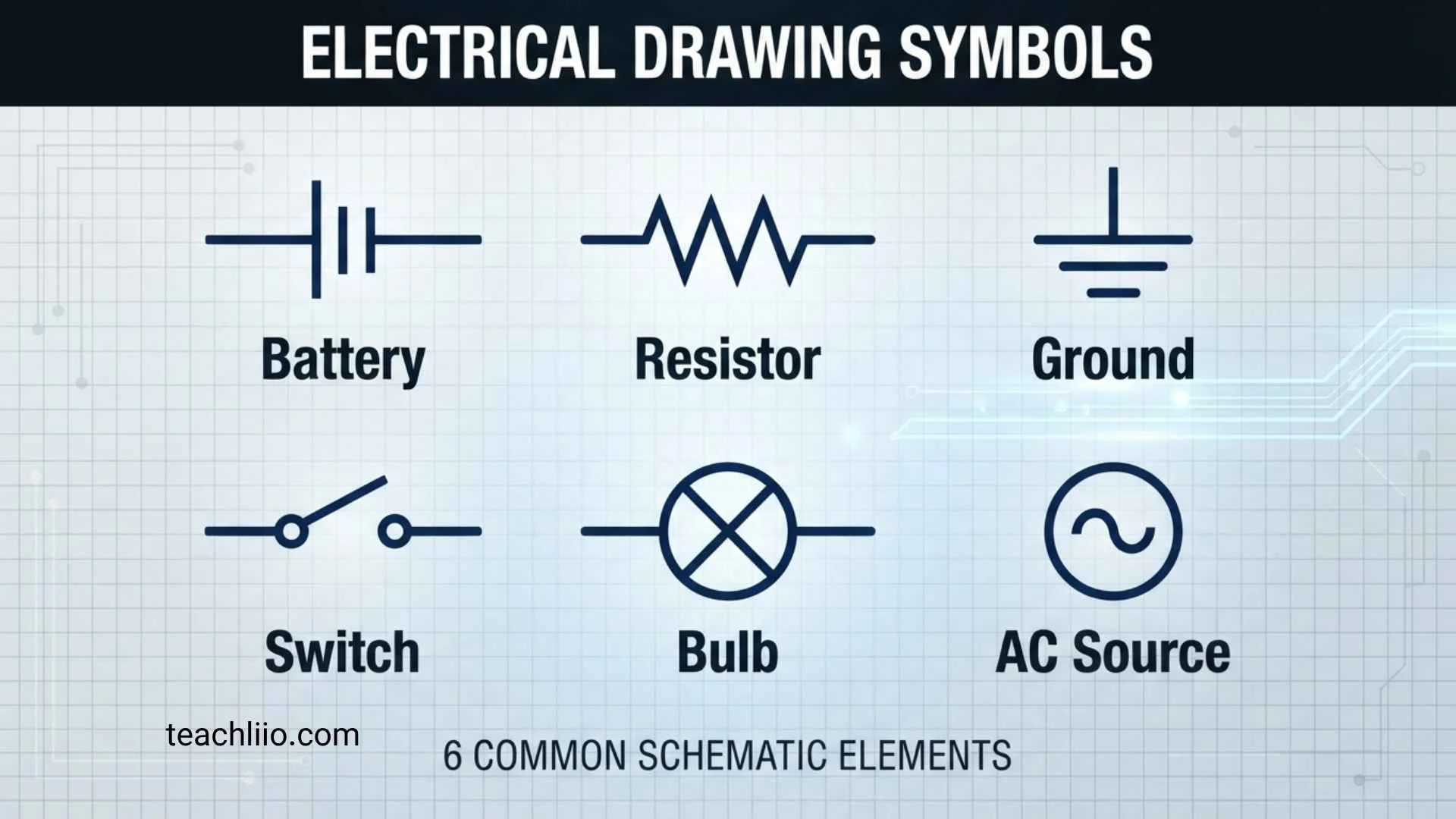
Electrical drawings can look complicated at first because they use symbols instead of writing the full name of every component. A small circle, line, rectangle, switch mark, or letter may represent an outlet, light, breaker, motor, transformer, or another part of an electrical system.
Electrical drawing symbols are graphical representations used to identify electrical components, connections, equipment, controls, and functions on drawings. They appear in electrical schematics, wiring diagrams, building plans, single-line diagrams, control drawings, and other technical documents.
The most important thing to remember is that electrical symbols are not completely universal. Standards, industries, countries, CAD libraries, and individual projects can use different conventions. IEC 60617 is an important international reference and its 2026 database contains more than 1,500 graphical symbols for electrotechnical diagrams.
For that reason, use the symbol legend supplied with your drawing first, then use a general symbol guide to understand unfamiliar marks.
Electrical Drawing Symbols Quick Reference Chart
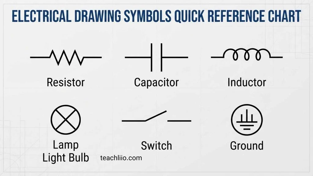
The fastest way to understand an electrical drawing is to identify the symbol, determine its name, and then understand its function.
Because graphical symbols can vary between standards, the text descriptions below focus on the component and its purpose rather than pretending that one visual shape is correct for every drawing.
| Symbol / Designation | Component | What It Means |
| ───── | Wire / conductor | Carries electrical current between points |
| ● | Junction / node | Indicates an electrical connection in many schematics |
| ⏚ | Earth / ground | Indicates an earth or grounding connection |
| —o/ o— | Open switch | Circuit path is open |
| —o—o— | Closed switch | Circuit path is closed |
| R | Resistor | Limits or controls current |
| C | Capacitor | Stores electrical energy |
| L | Inductor | Stores energy in a magnetic field |
| D | Diode | Primarily permits current in one direction |
| LED | Light-emitting diode | Produces light when energized |
| F | Fuse | Provides overcurrent protection |
| CB | Circuit breaker | Opens a circuit under specified fault or overload conditions |
| T | Transformer | Transfers electrical energy between circuits |
| M | Motor | Converts electrical energy into mechanical motion |
| G | Generator | Converts mechanical energy into electrical energy |
| S / SW | Switch | Opens or closes a circuit |
| K | Relay / contactor designation | Used for control switching in many drawings |
| A | Ammeter | Measures current |
| V | Voltmeter | Measures voltage |
| W | Wattmeter | Measures electrical power |
| BAT | Battery | Provides DC electrical energy |
| X / TB | Terminal | Connection point for conductors |
| JB | Junction box | Enclosure for electrical connections |
| DB | Distribution board | Distributes power to multiple circuits |
| PB | Push button | Momentary control switch |
| NO | Normally open contact | Contact is open in its normal state |
| NC | Normally closed contact | Contact is closed in its normal state |
The exact graphical appearance should always be verified against the drawing legend. Electrical diagrams commonly use standardized symbols, lines, and nodes to communicate circuit relationships.
What Are Electrical Drawing Symbols?
Electrical drawing symbols are visual shorthand.
Instead of writing “single-pole switch controlling a lighting fixture,” a designer can use a recognized switch symbol connected to a lighting symbol with a line.
This makes large drawings easier to read and allows electricians, engineers, designers, technicians, inspectors, and contractors to communicate using a compact visual language.
Electrical symbols can represent:
- Power sources
- Wires and cables
- Switches
- Lights
- Receptacles
- Circuit breakers
- Fuses
- Motors
- Generators
- Transformers
- Relays
- Contactors
- Resistors
- Capacitors
- Inductors
- Diodes
- Measuring instruments
- Grounding systems
- Panels
- Junction boxes
- Communication equipment
- Fire alarm devices
- Security equipment
A schematic generally focuses on how components connect and function, while a wiring diagram can provide more information about physical connections and arrangement. Electrical plans, meanwhile, commonly show where electrical devices are located within a building.
Types of Electrical Drawings and the Symbols They Use
Understanding the type of drawing you are looking at is just as important as recognizing individual symbols.
Electrical Schematic Symbols
A schematic focuses on the logical operation and electrical relationships of a circuit.
Common schematic symbols include:
- Resistors
- Capacitors
- Inductors
- Diodes
- Switches
- Relays
- Transformers
- Motors
- Batteries
- Ground
- Fuses
- Circuit breakers
The physical location of each component is usually less important than the way the components connect.
Electrical Wiring Diagram Symbols
A wiring diagram provides more detail about actual wiring and connections.
You may see:
- Wire numbers
- Terminals
- Connectors
- Switches
- Outlets
- Lights
- Equipment
- Cable connections
- Wire routes
Wiring diagrams are especially useful when tracing how equipment is physically connected.
Electrical Floor Plan Symbols
Electrical floor plans place electrical devices on an architectural layout.
Common examples include:
- Ceiling lights
- Wall lights
- Switches
- Receptacles
- Panels
- Junction boxes
- Smoke detectors
- Data outlets
- Telephone points
- Emergency lights
Construction drawings use symbols to communicate the general layout, equipment, fixtures, fittings, and routing of electrical systems.
Single-Line Diagram Symbols
A single-line diagram simplifies an electrical power system.
It can show:
- Utility supply
- Generator
- Transformer
- Busbar
- Circuit breaker
- Disconnect
- Current transformer
- Voltage transformer
- Panel
- Motor
- Major loads
- Grounding
Instead of drawing every conductor separately, the diagram uses a simplified representation to show the overall distribution system.
Ladder and Control Diagram Symbols
Control diagrams commonly use:
- Normally open contacts
- Normally closed contacts
- Relay coils
- Contactor coils
- Push buttons
- Selector switches
- Timers
- Overload contacts
- Limit switches
- Motor-control components
These symbols help show the logic used to control motors, machinery, and other electrical equipment.
Basic Electrical Circuit Symbols
The following categories contain many of the symbols beginners encounter first.
Wire and Connection Symbols
A straight line commonly represents a conductor.
Other connection symbols may indicate:
- Connected wires
- Crossing wires
- Unconnected wires
- Junctions
- Terminals
- Cable connections
- Busbars
- Ground connections
A small dot is commonly used to show a junction where conductors are electrically connected, although the drawing’s conventions should always be checked. Autodesk similarly describes nodes as junctions where circuit elements are joined, often represented by a small dot.
Power Source Symbols
Power sources can include:
- AC supply
- DC supply
- Battery
- Cell
- Generator
- Solar source
- Power supply
- External supply
Battery symbols commonly use alternating long and short parallel lines. Power-supply symbols may instead use a label, terminal designation, or specialized graphical representation.
Ground Symbols
Grounding symbols can represent:
- Earth ground
- Protective earth
- Chassis ground
- Signal/common reference
- Equipment grounding
Do not automatically assume that every symbol containing horizontal lines represents exactly the same type of grounding.
The drawing legend and project documentation should identify the intended meaning.
Passive Component Symbols
Passive components are fundamental to many electrical and electronic diagrams.
Resistor Symbols
A resistor limits or controls current.
Two common graphical conventions are associated with resistor symbols:
- A zigzag form commonly seen in North American-style schematics
- A rectangular IEC-style form
This is a good example of why recognizing the function of a symbol can be more useful than memorizing only its shape.
Capacitor Symbols
A basic capacitor is generally represented by two conductive plates separated by a gap.
You may encounter symbols for:
- Fixed capacitors
- Variable capacitors
- Polarized capacitors
- Electrolytic capacitors
Additional markings may identify capacitance, voltage rating, polarity, or other characteristics.
Inductor Symbols
An inductor is commonly shown as a series of curved loops or coils.
It stores energy in a magnetic field and appears in power supplies, filters, control circuits, and other electrical or electronic applications.
Switch and Control Symbols
Switches are among the most frequently encountered electrical drawing symbols.
Single-Pole Switch
A single-pole switch controls a circuit by opening or closing its electrical path.
On architectural plans, a switch may be accompanied by a designation showing the type of control.
SPST Switch
SPST means single-pole, single-throw.
It provides a basic on/off switching function.
SPDT Switch
SPDT means single-pole, double-throw.
It allows one common connection to be switched between two possible paths.
Push Button Symbols
Push buttons can be:
- Normally open
- Normally closed
- Momentary
- Emergency stop
- Illuminated
Their normal state matters when interpreting a control circuit.
Selector Switch Symbols
Selector switches allow an operator to choose between two or more operating positions.
They are frequently found in:
- Motor controls
- Industrial machinery
- Control panels
- Automation systems
Electrical Protection Symbols
Protection devices help show how a circuit is protected from specified electrical faults or abnormal conditions.
Fuse Symbol
A fuse is represented by a dedicated protective-device symbol and is normally associated with an overcurrent protection function.
The drawing may also show its:
- Rating
- Reference designation
- Type
- Circuit number
Circuit Breaker Symbol
Circuit breakers are commonly shown in power-distribution drawings and control systems.
A drawing may identify:
- Single-pole breaker
- Two-pole breaker
- Three-pole breaker
- Main breaker
- Molded-case breaker
- Miniature circuit breaker
The symbol identifies the device, while labels provide information such as rating and circuit designation.
Disconnect Switch Symbol
A disconnect or isolating device is used to indicate a means of separating equipment or a circuit from its electrical supply.
Its exact graphical representation depends on the drawing convention.
Lighting and Electrical Plan Symbols
Electrical plans use symbols to show where equipment is installed rather than only explaining circuit operation.
Light Fixture Symbols
Common lighting categories include:
- Ceiling light
- Recessed light
- Pendant light
- Wall-mounted fixture
- Emergency light
- Exit light
- Floodlight
- Outdoor fixture
- LED fixture
- Track light
The symbol normally indicates the location or type of fixture, while schedules may provide additional information.
Outlet and Receptacle Symbols
Common receptacle categories include:
- Standard receptacle
- Duplex receptacle
- Single receptacle
- GFCI/GFI receptacle
- Floor outlet
- Weather-resistant outlet
- Dedicated equipment outlet
- USB receptacle
Because architectural conventions differ, the project legend should identify the exact receptacle type.
Panel and Junction Box Symbols
Panels and junction boxes are frequently identified with abbreviations such as:
- DB
- DP
- LP
- PP
- JB
These abbreviations are not universal, so their meaning should be confirmed from the project’s abbreviation schedule.
Industrial Electrical Drawing Symbols
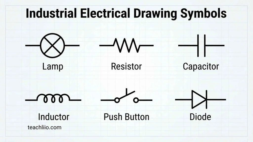
Industrial drawings require additional symbols because they often describe control logic as well as power distribution.
Normally Open and Normally Closed Contacts
A normally open (NO) contact is shown in its normal, de-energized state as open.
A normally closed (NC) contact is shown in its normal state as closed.
These states are critical when reading relay and motor-control circuits.
Relay Symbols
A relay diagram may contain:
- Relay coil
- NO contact
- NC contact
- Changeover contact
- Timer contact
The coil and its associated contacts work together as part of the control system.
Contactor Symbols
Contactors are commonly used to switch larger electrical loads.
A contactor diagram may show:
- Coil
- Main contacts
- Auxiliary NO contacts
- Auxiliary NC contacts
They are particularly common in motor-control circuits.
Overload Relay Symbols
An overload relay is commonly associated with motor protection.
The control drawing may show its auxiliary contact separately from the power circuit.
Limit Switch Symbols
Limit switches detect the position or movement of machinery.
They are frequently used in:
- Industrial machines
- Conveyor systems
- Doors
- Lifts
- Automated equipment
Solenoid Symbols
A solenoid represents an electrically operated device that produces mechanical movement.
Solenoids may be used to operate valves, locks, actuators, and other mechanisms.
Terminal Block Symbols
Terminal blocks provide organized connection points for wiring.
They are especially common in:
- Control cabinets
- Industrial panels
- Machinery
- Automation systems
Single-Line Diagram Symbols
Single-line diagrams deserve special attention because they provide a high-level view of electrical power distribution.
Common symbols and designations include:
| Component | Typical Function |
| Utility source | Incoming electrical supply |
| Generator | Backup or onsite generation |
| Transformer | Changes voltage level |
| Busbar | Common electrical distribution point |
| Circuit breaker | Switching and protection |
| Disconnect | Isolation |
| CT | Current transformer |
| PT/VT | Voltage transformer |
| Motor | Electrical load |
| Panel | Distribution equipment |
| Capacitor bank | Power-system application |
| Ground | Grounding connection |
The purpose of a single-line diagram is not to reproduce every physical wire. Instead, it provides a simplified picture of the major electrical relationships in the system.
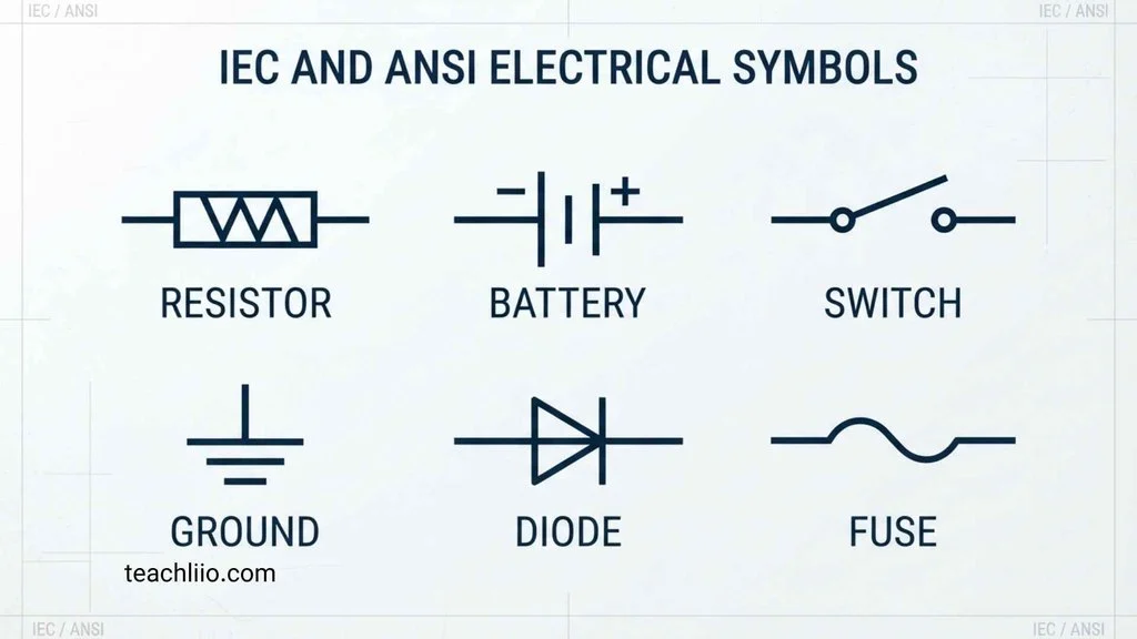
IEC and ANSI Electrical Symbols
One of the most important points for anyone learning electrical symbols is that different conventions exist.
IEC 60617 is the IEC database for graphical symbols used in electrotechnical diagrams. The current database contains more than 1,500 symbols and covers conductors, passive components, semiconductor devices, electrical-energy conversion, switchgear, protection, measurement, signalling, telecommunications, and architectural installation plans.
Older North American drawings may also contain conventions associated with IEEE/ANSI 315. However, IEEE currently lists IEEE/ANSI 315-1975 as an Inactive-Reserved Standard, so it should not be presented as a currently active standard in the same way as IEC 60617.
The practical lesson is simple: do not identify a symbol only from a generic chart when working from an actual project drawing. Check the drawing legend, notes, standards, and title block.
Common Electrical Symbols That Beginners Confuse
Some symbols are easy to misunderstand because they look similar or their meaning depends on context.
Connected Wires vs. Crossing Wires
A crossing line does not automatically mean that two conductors are electrically connected.
Look for the drawing’s connection convention, such as a junction dot or another specified indication.
Normally Open vs. Normally Closed Contacts
These represent opposite normal states.
Always determine whether the contact is shown in its normal condition before interpreting how the circuit operates.
Earth Ground vs. Other Ground References
Ground symbols can represent different electrical references.
Use the legend and circuit context to determine whether the symbol represents protective earth, chassis ground, signal reference, or another grounding concept.
Resistor Shapes in Different Standards
A resistor may appear as a zigzag line in one convention and a rectangle in another.
The different appearance does not necessarily mean that the components perform different functions.
Switch Symbols vs. Relay Contacts
A manually operated switch and a relay-controlled contact can look related but have different roles.
The surrounding circuit and reference designation help identify which type is being used.
Electrical Drawing Abbreviations and Reference Designations
Symbols are only part of the language used in electrical drawings.
You may also see abbreviations such as:
| Abbreviation | Common Meaning |
| A | Ammeter or ampere, depending on context |
| CB | Circuit breaker |
| C | Capacitor or other project-specific designation |
| DB | Distribution board |
| F | Fuse |
| G | Generator |
| JB | Junction box |
| K | Relay/contactor designation in many conventions |
| L | Inductor, lamp, line, or project-specific designation |
| M | Motor |
| PB | Push button |
| R | Resistor or relay, depending on convention |
| S / SW | Switch |
| T | Transformer |
| TB | Terminal block |
| V | Voltmeter or voltage |
| CT | Current transformer |
| VT | Voltage transformer |
These abbreviations can vary by discipline and project.
For example, the letter L might mean different things in different drawing contexts. Therefore, reference designations should never be interpreted without checking the drawing’s legend when there is uncertainty.
How to Read Electrical Drawing Symbols Step by Step
You do not need to memorize hundreds of symbols before you can understand an electrical drawing.
Start With the Drawing Legend
Find the electrical legend, symbols schedule, abbreviations, or notes.
This should be your primary reference.
Identify the Drawing Type
Ask whether you are looking at:
- A schematic
- Wiring diagram
- Floor plan
- Single-line diagram
- Control diagram
- Panel schedule
- Equipment diagram
This immediately narrows down the possible meanings.
Identify the Major Components
Find the obvious equipment first:
- Panel
- Transformer
- Motor
- Generator
- Main breaker
- Lights
- Receptacles
Then move toward smaller control components.
Follow the Lines
Trace the electrical connections from the source toward the load.
Look for junctions, terminals, switches, protective devices, and equipment.
Read Reference Numbers
Labels such as M1, CB1, T1, R1, or similar designations help distinguish one component from another.
Check the Schedules
Panel schedules, equipment schedules, fixture schedules, and circuit schedules often provide information that cannot fit directly beside a symbol.
Compare the Drawing With Related Sheets
Large projects may divide information among:
- Lighting plans
- Power plans
- Fire alarm drawings
- Riser diagrams
- Single-line diagrams
- Control diagrams
- Panel schedules
Looking at only one sheet can sometimes leave important information unexplained.
Common Mistakes When Reading Electrical Symbols
Assuming Every Symbol Is Universal
Symbols can vary between standards and project conventions.
Ignoring the Legend
A generic internet chart should not override the project’s own legend.
Confusing a Schematic With a Floor Plan
A schematic emphasizes electrical relationships, while a floor plan emphasizes physical locations.
Treating Every Crossing Line as a Connection
Always check the connection convention.
Ignoring Reference Designations
Letters and numbers often provide important information about individual components.
Looking Only at the Symbol
A symbol’s surrounding labels, notes, line types, and schedules can change how it should be interpreted.
Mixing Different Standards
Do not combine IEC, North American, legacy, and project-specific conventions without verifying which system the drawing uses.
Which Electrical Symbols Should Beginners Learn First?
If you are new to electrical drawings, start with the symbols you are most likely to encounter.
A useful beginner sequence is:
- Wire
- Junction
- Ground
- Battery
- AC/DC source
- Switch
- Resistor
- Capacitor
- Inductor
- Diode
- LED
- Fuse
- Circuit breaker
- Transformer
- Motor
- Generator
- Relay
- Contactor
- Light
- Receptacle
Once these become familiar, move into specialized industrial, automation, power-distribution, fire-alarm, communication, and building-plan symbols.
Tips for Using an Electrical Symbols Chart
A good electrical symbols chart should be used as a reference tool, not as a replacement for the project documentation.
When checking an unfamiliar symbol:
- Find the symbol on the drawing.
- Check the legend.
- Read the abbreviation or reference designation.
- Follow the connected lines.
- Identify the drawing type.
- Check associated notes.
- Review the relevant schedule.
- Compare the symbol with the applicable standard when necessary.
This approach is much safer than searching for a similar-looking symbol and assuming that it has the same meaning.
Why Electrical Drawing Symbols Matter
Electrical drawings provide a compact way to communicate complicated systems.
A complete drawing set may contain power layouts, floor plans, riser diagrams, single-line diagrams, control wiring, schedules, and other documentation. Symbols connect these different forms of information by providing a consistent visual language.
For electricians, symbols can help with installation and troubleshooting. For engineers, they help communicate design intent. For students, they provide a foundation for understanding circuits. For contractors and designers, they make large construction projects easier to coordinate.
Learning symbols therefore means learning more than a collection of shapes. It means learning how electrical information is organized.
Frequently Asked Questions
What are electrical drawing symbols?
Electrical drawing symbols are graphical representations used to identify electrical components, equipment, connections, controls, and functions on electrical drawings.
What are the most common electrical drawing symbols?
Some of the most common include wires, junctions, ground, switches, lights, receptacles, resistors, capacitors, fuses, circuit breakers, transformers, motors, generators, relays, and contactors.
What is the symbol for a circuit breaker?
A circuit breaker has a standardized graphical representation that varies according to the drawing convention. Its reference designation, such as CB, may also appear beside it. Always check the drawing legend for the exact graphical form.
What is the difference between an electrical schematic and a wiring diagram?
A schematic primarily shows the logical operation and electrical relationships of a circuit. A wiring diagram generally provides more information about physical wiring, connections, and component arrangement.
Are electrical drawing symbols universal?
No. Many symbols are standardized, but different standards, regions, industries, software libraries, and project conventions can produce variations. IEC 60617 is a major international reference for electrotechnical diagram symbols.
What is IEC 60617?
IEC 60617 is the IEC database of graphical symbols for diagrams. The current database contains more than 1,500 symbols covering a wide range of electrotechnical applications.
Are ANSI and IEC electrical symbols the same?
Not always. Some components have different graphical conventions under different standards. The meaning can remain similar even when the visual representation changes.
What does a dot mean on an electrical drawing?
A dot commonly indicates an electrical junction where conductors are connected. However, the drawing’s own legend and connection conventions should be checked.
What does NO mean on an electrical drawing?
NO commonly means normally open. It indicates that a contact is shown open in its normal state.
What does NC mean on an electrical drawing?
NC commonly means normally closed. It indicates that a contact is shown closed in its normal state.
What is a single-line diagram?
A single-line diagram is a simplified representation of an electrical power system. It can show major sources, transformers, switchgear, breakers, busbars, panels, motors, and other equipment without drawing every conductor separately.
Where can I find the meaning of an unfamiliar electrical symbol?
Start with the drawing’s symbol legend or electrical notes. Then check the abbreviation schedule, related drawings, equipment schedules, and applicable standards.
Can beginners learn electrical drawing symbols?
Yes. Start with common wires, switches, lights, outlets, breakers, fuses, grounding, transformers, motors, and control symbols. Practice reading complete drawings rather than memorizing symbols in isolation.
Why do electrical symbols look different on different drawings?
Different standards and drawing conventions may use different graphical representations. IEC 60617, legacy North American conventions, and project-specific CAD libraries can produce variations. IEEE currently lists IEEE/ANSI 315-1975 as inactive-reserved, so its historical conventions should be treated accordingly.
Conclusion
Electrical drawing symbols provide the visual language used to communicate electrical systems on schematics, wiring diagrams, construction plans, control drawings, and single-line diagrams.
The most useful way to learn them is not to memorize hundreds of shapes at once. Start with the common symbols for wires, junctions, grounding, switches, lights, outlets, resistors, capacitors, fuses, breakers, transformers, motors, relays, and contactors. Then expand into industrial controls, power-distribution equipment, building plans, and specialized systems.
Remember that the same component can have different graphical representations depending on the standard and drawing type. IEC 60617 provides an extensive international reference, while older North American drawings may contain conventions associated with IEEE/ANSI 315, which IEEE now identifies as inactive-reserved.
Most importantly, always check the electrical drawing legend before relying on a generic symbol chart. The legend, notes, reference designations, line conventions, and schedules together provide the context needed to interpret a drawing accurately.
Once you understand that system, electrical drawings become much easier to read. What initially looks like a collection of confusing lines and shapes becomes a structured map showing where components are located, how they connect, and how the electrical system is intended to operate.
